- Stabile entro ± 0,01% all'anno
- 18 valori dei modelli da 1 μH a 10 H
- Basso coefficiente di temperatura noto
- 3 anni di garanzia inclusi
- Calibration accredited to ISO-17025 included
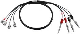
- Minimized connection errors
- Toroidal - free from external fields
Why Buy the 1482 Standard Inductor?
- Highly stable over time with over 60 years of history
- The inductance standard used by most major and national calibration laboratories worldwide see CCEM WGKC/2001-15 link below
- Insensitive to applied voltage and current
- Numerous papers have been written outlining various characteristics of the 1482s
Introduction
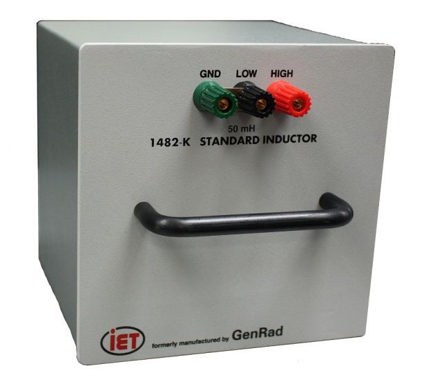
The GenRad 1482 Standard Inductors are the standard of choice in metrology labs. Used today by national metrology institutes and primary standards bodies around the world, these inductors have no peer or equivalent.
IET continues to produce the 1482 standard inductors to the same exacting specs as General Radio. These standard inductors are accurate, highly stable standards of self inductance for use as a low frequency reference or working standard in the laboratory.
Story of the IET (GenRad) Model 1482 inductor
In 1952 GenRad introduced the 1482 Series of Standard Inductors as a replacement for the GenRad 106 Series of Standard Inductors .
The GenRad 1482 was far superior to the 106 Series of Standard Inductors due to improvements in TC, and insensitivity to electrical environment and ambient humidity.
GenRad also manufactured a 1481 Series of fixed toroidal inductors. These inductors are wound on a ferromagnetic core which makes the 1481 smaller in physical size however the inductance changes with current flowing through the inductor.
The quest for an ideal inductor (well almost)
Ever since the basic electrical components, R, L*, and C (Resistance, Inductance and Capacitance) have been understood, it has been known that physical implementations of the of the three components can be far from ideal.
Of the three RLC elemental components, the inductor is the least ideal. An ideal inductor would need to have no resistance, and no capacitance components, dimensionally stable, be insensitive to orientation and external magnetic fields, temperature, and aging.
For example, it is easier to construct a capacitor with an almost ideal dielectric by using air, but inductors require real wire with finite resistance. Also at issue are; the capacitance of the physical construction, field geometry, pickup, frequency response, magnetic saturation, and temperature coefficient.
How did GenRad solve these problems
The 1482 Standard Inductors are symmetrically wound toroids and have a much higher degree of astaticism than existed in previous inductors. GenRad went to extremes in this regarding and created a custom winding machine dedicated to winding these inductors.
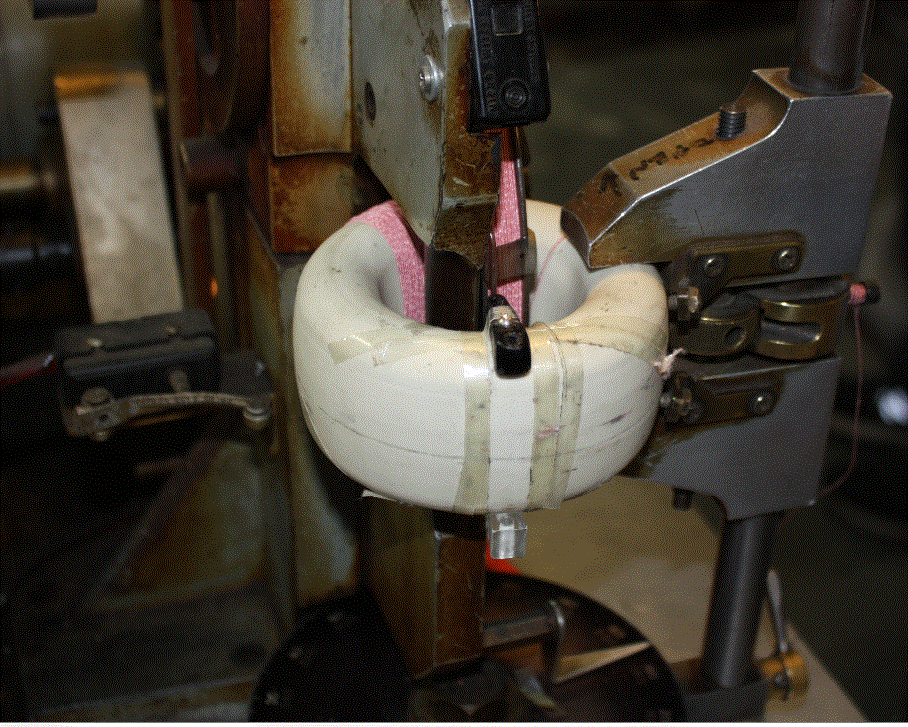
Core being wound on the GenRad winding machine at IET Labs
IET Labs still maintains and uses the 3 winding machines originally used at GenRad.
The 1482 Standard Inductor uses Litz wire . The Litz wire is wound in duplex on a steatite core. The duplex winding minimizes pick-up from external electromagnetic fields and the inductor produces no external magnetic field.
The Steatite L-5 ceramic core has low thermal expansion and an elliptical cross section to avoid sharp bends in the winding.
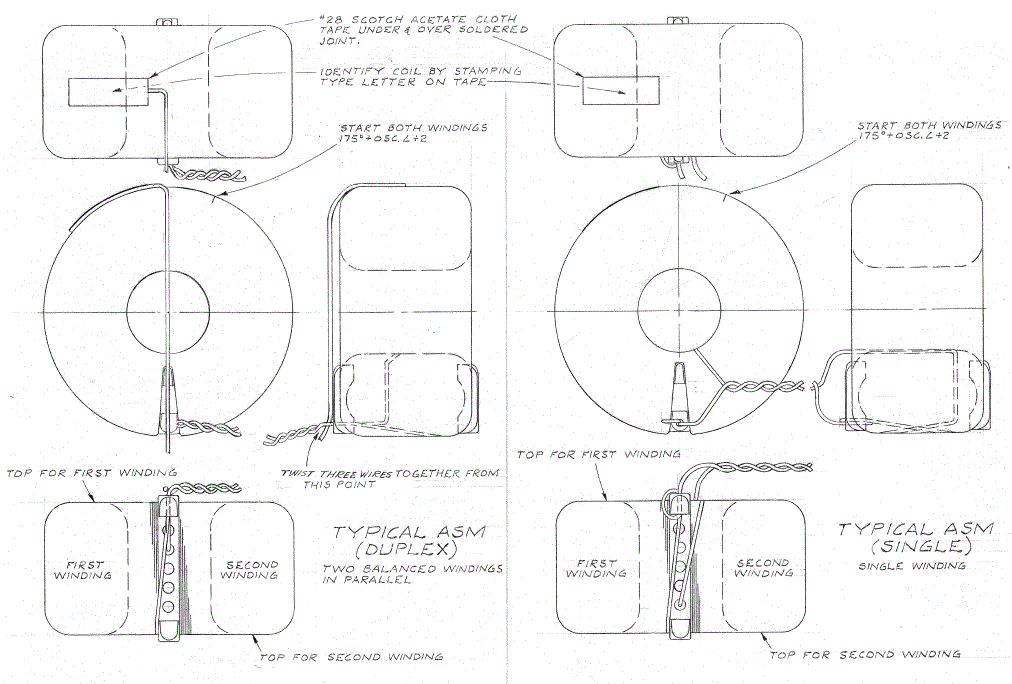
Duplex Winding Drawing
Once the cores have been wound they are aged over several days to improve the stability. The cores are then potted in a box containing ground cork and desiccant to provide cushioning and effectively “float” the inductor to improve stability.
Even the position of this assembly when placed into the aluminum housing is taken into account to improve characteristics.
Once the box and inductor have been positioned the housing, a potting compound is poured into the housing to effectively “hermetically seal” the inductor and minimize affects due to humidity.
For inductance values of 500 µH or less, the 1482 Standard inductors are delivered with 6 gold plated low thermal emf binding posts for connection . This allows both the inductance L and the zero inductance Lo to be measured without moving cables which would introduce errors. A shorting link is move between Lo and L depending upon which inductance is being measured. The algebraic difference between L and Lo is the calibrated value of the inductor.
For inductance values greater than 500 µH, the 1482 Standard inductors are delivered with 3 gold plated low thermal emf binding posts.
For comparing other inductors with these standards using transfer method, the 1689 or 1693 Digibridge is recommended.
More information on the design of the 1482 Standard Inductor can be found at
GenRad Nov. 1952 Experimenter
B-12 Publication - Determining Resonant Frequency of the 1482
The 1482 Inductors have an extensive history of calibration by premier calibration laboratories which is detailed in;
CCEM WGKC/2001-15 International Comparison of 10 mH 1482 Inductance Standards at 1 kHz
One of the great advantages of the 1482 is the number of papers detailing various characteristics of the 1482 such as this this paper detailing errors due to connections;
Influence of Adaptors on the Calibration of Inductance Standards
1482 Inductance Standard Basic Specifications
(Full specifications can be found on the datasheet)
Calibration: A certificate of calibration, that is accredited to ISO-17025, is provided with each unit, giving measured values of inductance at 100, 200, 400, 1000 Hz for all inductance values and an additional value at 10 kHz for inductance values < 2 mH, with test conditions and method of measurements specified. The calibrate inductance values are obtained by comparison for most values, to standards that whose absolute values are traceable to the International System of Units (SI) through an NMI mainly NPL. Measurement uncertainties are typically better than ±0.02% at all frequencies and are listed on the certificate of calibration.More information on inductance calibration can be seen at IET Labs inductance calibrationStability: Inductance change is less than 0.01% per year.Temperature Coefficient of Inductance: Approximately 30 ppm/°C. Small temperature corrections may be computed from resistance changes. A 1% increase in resistance, produced by temperature increase of 2.54°C corresponds to 0.0076% increase in inductance.Resonant Frequency: See table in datasheet for representative values. A measured value is given on the certificate of calibration. Effective series inductance increases with frequency and this is detailed in GR Experimenter Nov. 1952. Typically a 1% increase in inductance can be expected if used at 1/10th of resonant frequency.Terminals: 5-way gold-plated, tellurium-copper binding posts that feature low resistance. Terminals have standard ¾-in spacing with removable gold-plated ground strap. Dimensions: 16.6 cm H x 16.6 cm W x 20.4 cm D (6.5" H x 6.5" W x 8" D) Weight: 5.3 kg (11.5 lb) net, 6 kg (13 lb) shipping

